
PLACEHOLDER
Edited: -
ELECTRON GUNS
For dummies :-)
So, you like guns?..
Ah, but they're restricted/illegal in your boring country?
Same... but y'know, there's options...
What about I tell you... you can build your own!
Now, don't get too excited. Sadly I am not talking about firearms here, that would be cool but I am sure there's much better tutorials to be found about those. Besides, you'd still have to jump through a lot of hoops to get the bullets. Our gun's won't be shooting lead (for now), they'll shoot electrons!
Historical perspective
Now, whenever I mention the word "electron", you've probably come across it before. Whether it be a wave or a particle, often dangling around the core of an atom in a cloud of uncertainty, what we can say for certain is that it has a measurable mass and an electric charge. And despite they've been around for as good as all eternity, it is only relatively recent a couple clever scientists figured out they exist, more importantly what they are, how they interact and how they behave, and of course, how to put them to good use
Only the fundamentals are within the scope of this piece, we are going to dive down into electron guns specifically, and we will also briefly discuss the detection of these electrons in free space. This means we should cover things like how to practically push an electron into free space, how to control its position through acceleration, and its interaction with other particles. This is a very mature technology already, with most of the development having taken place between the mid 1800s and mid 1900s. It is hard to properly credit every influential person, but if you want a further read, then I highly recommend referencing William Crookes, being the founding father of pulling electrons off a conductor into a free partial vacuum, Ferdinand Braun, for innovations introducing a homogeneous phosphorus screen and optimizing tube geometry for deflection and Sir Joseph John Thomson, for introducing electrostatic deflection plates to the equation. A.k.a the very fundamentals of interaction with electrons using electromagnetic and electrostatic fields, plus a good reliable method of properly resolving the electrons positions whilst all combined, being proven to be incredibly useful in many fields of science, motivating further leaps of research.
Electron gun
To pull the band-aid off the wound, I've coined the term electron gun many times already without mentioning what it is. It is quite simply put a device which pulls electrons out of a medium and accelerates them into a controlled beam. What medium, how fast the electrons go, and how fine this beam is depends on the task at hand. In the Cathode Ray Tube or CRT of an oscilloscope or television, we don't necessarily need a very well focused beam of electrons, but we do want a very high beam current to produce good light output. The "gun" in a beam tetrode tube needs to be relatively homogeneous and wide such that high linearity can achieved in its amplification. In a vidicon tube, we may optimize for high linearity of the deflection whilst in an electron microscope, we do not need a high beam current as it would ruin the sample, yet to be able to resolve images better than an optical microscope possibly can, we do want an incredibly finely focused beam.
On this subject, I think the most honourable mentions by far you can't come across in literature enough, is the work of the incredible engineer, Philo Farnsworth. Not only was he the first to build full electronic television set, he was also a very early pioneer in the development of image capture tubes and electron microscopes. He's the living testament of what can be done at a young age when you're not tied to the strings of the academic world, whilst having people around that are willing to invest into development instead! Another such influential figures was Vladimir Zworykin, another early televison and camera engineer with a similar portfolio.

Sources
There's so much information to tell, I could write a book about this... But there's no need to since there were many engineers back in the day that did already. Buy those books, and read those books! I won't be telling anything new necessarily, but I hope to put everything into a good format such that anyone can design their own electron gun (which, having typed that sentence, won't be many, but who knows may this inspire people to try similar projects to me for themselves).
In most countries in the developed world, good books have probably been written about the subject. What I found most important is that you find books that were written by engineers rather than physicists. This isn't a personal attack, trust me, I've endured education in both subjects, miserably failing both equally, but it is objective truth that the guys realizing working systems are probably better at explaining how to design your own electron optics than someone who only wrestles formulas all day would. Just briefly check the authors on the internet, don't compromise like I did because you will end up with bookshelf material... as in, it will never leave the shelf that is... This will most likely strand in two types of books, either general ones with a title similar to "Electron Optics", or ones from purely the television world. Both types are incredibly useful, try to find something up until around the 1960s - 1970s. Up until here, books were written such that you don't need to use Computer Aided Design, CAD. These designs, however, are usually so matured, whatever came after are optimizations of these old topologies rather than entirely new ones. This because electron gun design was used in so many different fields of electronics, there was an unmatched amount of engineers digging into the same subject, from here on little extra progress was realistically needed to be made anymore. The titles I got the majority of my information from is from the books in the picture below unless stated otherwise.

A watchful eye notices at this point probably the various languages my bookshelf contains. I'm not going to push this weird diversity obsession onto you all that's trending right now. The entire reason is mostly money related. Obviously I'd prefer all book titles in Dutch, but for some reason here, books about electron optics are hard to find or brutally expensive. I bought the "TELEVISIE" one at a radio convention, a good second hand book shouldn't have to cost you more than a couple euros/bucks/quid. Cool thing about Poland is, I'm a very frequent visitor of the country and there's a great selection of online "antykwariat" available (which seems to be quite trendy in many other Slavic countries), where rather than throwing old books out, they're collected and resold for about the cost it takes to publish the book titles on a website. So... if you want to unlock a LOT of older information for super cheap, learn a Slavic language :-). Great info, low prices and a big selection, what more do you need???
Another good way to select good books is to look at the aesthetics of the book. Here I am not talking about cover art, but mostly how worn the book is. You probably immediately would choose the one in the best condition with the nicest looking cover. But keep in mind there IS a reason why it still looks pristine 50 years later. It was probably quite useless and never really read. A good book gets carried everywhere, coffee is spilled on, has a warped cover, tears in pages, etc. The worse they essentially look, the better the information probably is, and luckily also, they're often sold for much less as well!! Score!
Pushing electrons into aether
Enough talk. I will discuss with you ONE electron gun design which is a great balance between ease of construction, but good flexibility. Since electromagnets are nowadays quite difficult to make due to restrictions in materials (electrical steel is SUPERBLY hard to get your hands on), I will purely take an electrostatic approach. Of course you can get clever, use focusing magnets from an old electron microscope, or even better, magnetically focused old television sets. And whilst I am a big pro for reusing old materials like this, I am also severely against pulling good antiques apart for a what's most likely going to be a never ending project. Thus, you should be able to build this with easily accessible materials, and YOU can decide whether you want to scoop in repurposed commercial parts instead. I will discuss magnetic here, mostly looking at magnetic deflection, but I will briefly mention electromagnetic optics as well.
To play with electrons in free space, we need a vacuum. This isn't any ol' vacuum you can get with a refrigerator compressor, these vacuums are of the level where material choice becomes important, not for mechanical stability, but for the quality of the vacuum. We speak of systems with a rough vacuum achieved with scroll-, membrane-, or rotary vane pumps, and high vacuums achieved through the use of a turbo molecular-, oil diffusion- or mercury diffusion pump. If you haven't heard of this kind of stuff, I'd like to refer you to the VACUUM tab (which is not written yet). If you can't achieve vacuums around at least absolute bare minimum of 1E-5 mBar, this read is either just for fun or for a school report. This partly because there's no point to free electrons if they're going to crash into molecules anyways, and that we are dealing with high voltages and if your vacuum setup is incredibly minimal, you may result into making a more dangerous environment than simply running your setup in air (Google Paschen's law).
Keep in mind, electron optics is classical optics on steroids. This is because the refractive index of electrostatic (and electromagnetic) lenses is highly determined by the electron's energy/velocity. This means that the behaviour of the lens changes throughout the course of the electron through the lens. Besides this, we do not have the capability to accurately dial in the contours of an electron lens like we can do by polishing optical ones from glass (or other optically clear materials). This inherently makes electron lenses quite bad and introduces a bunch of other artifacts. Classical optics, especially with modern lenses, adheres incredibly close to theory, with electron optics, mathematics are more of an educated guess and is very experimental. Another limitation is that the medium for electron optics has to be a vacuum, this makes experimenting in and by itself quite difficult. A big benefit, however, is that through the use of plenty of variable power supplies, we CAN change the behaviour of the lens. Rather than parameterizing distances between lenses being sold with given focal lengths and sizes, we parameterize the acceleration potentials instead for fixed lengths.
To put it bluntly, this stuff is hard, and for someone like me who also struggles to understand the material, it is even harder to explain everything in a way everyone understands at a really low level. I hope you have a bit of mercy, so for the energy I put in to write everything down here, I think you should Google a crash course on classical optics and basic mathematics (rewriting formulas, learning about notation, low level trigonometry and exponentials etc.)
-----CATHODE-----
Voltage & Potential
Whenever is referred to a cathode, people may think we refer to the "negative" electrode in a system. Whilst not entirely false, I want to briefly clarify two things. "Voltage" in and by itself being a grammatically incorrect term but so heavily bastardized we all collectively get away with it, is quite a deceptive term. We may refer to the "voltage" of something, but it will quickly cause confusion since "voltage" is not an absolute quantity. Any voltmeter comes with two leads, we measure with respect to something. Sometimes it is called "earth", other times "chassis", and most often "ground". And whilst this convention works most of the time speaking about circuit design, for an electron gun this is not always as evident. A CRT of an oscilloscope may have its cathode hooked up to "negative" or ground. Then the anode voltage is positive, this is not an issue since the evacuated envelope of a picture tube is made of glass. If you want to do video modulation by changing the potential on the cathode however, it may be more convenient to hook up a different element to ground in the tube, or keep it floating entirely. In an electron microscope, the "highest" voltage of the main accelerating anode is hooked up to "ground" and we use a power supply to pull the cathode to a very big negative potential with respect to "ground".
Are you confused already? Good. This is why we ditch "voltage" as a term entirely in this article (you shouldn't use a unit as a quantity anyways, wattage, amperage, ohmage, c'mon guys, this is lazy, we have words for this!), we will only speak of the word "potential" a.k.a, the electromotive force ("voltage") between two points. (Obviously, I also use voltage everywhere else, I'm just as much of a herd animal as you all are, but when talking about electron optics it DOES get horribly confusing).
Besides this, the cathode does not NEED to be the most negative element in a system. In the case of an electron gun, this is almost always the modulation grid otherwise known as the Wehnelt cylinder. In vacuum tubes, this is often called the control grid. This grid generates a repelling force preventing the electrons to reach the anode depending on how negative the potential of this grid is with respect to the cathode. Thus, rather than thinking of the cathode as the "negative" electrode, let's think of it as the electrode which primary function is to emit electrons!
Thermionic Emission & Work Function
Of course there are multiple mechanisms to pull electrons off a cathode, whether it be by bombarding it with photons, or even with other electrons (secondary electron emission), the preferred and easiest method for the home brew hobbyist is through thermionic emission. Thermionic emission is the mechanism, where through the kinetic energy of particles caused by temperature, electrons can be kicked out into free space. This is often done with a directly heated cathode or indirectly heated cathode, where a directly heated cathode is usually a thoriated tungsten filament where the heating current is superposed onto the cathode supply (electron microscopes), and an indirectly heated cathode with an oxide layer often has an electrically insulated filament heating up the assembly (CRTs). The higher the temperature, the more electrons get kicked out and the bigger the cloud of electrons becomes around the cathode, the ease of which electrons get kicked off a material is called the work function. The work function is different for every material, but chosen properly, can severely increase the efficiency of the cathode. You can't infinitely heat up a wire because at some point the material is going to melt or evaporate.
The oxide coated cathodes are not interesting to look at as those are severely hygroscopic. Meaning once formed in a vacuum, when they're exposed to air they deteriorate rapidly. Hence, CRT repair businesses would often replace the entire gun with a new to-be-activated cathode. Since a CRT technically should technically maintain the its vacuum over its expected lifetime, this is no issue, but it does essentially renders the reuse of an electron gun from a CRT impossible if you don't figure out a way to overcome this hurdle. That's why for us, we are left with either the use of an inefficient tungsten filament, or a more efficient thoriated one. The thorium drastically lowers the work function, meaning that for the same amount of electrons, the temperature of the filament can be much lower, drastically improving the lifetime. The work function of pure tungsten is 4,54 whatever unit literature calls it, whilst that of thoriated tungsten is 2,63 whatever unit literature calls it. The lower the better. One may apply pure tungsten successfully without preparation. Thoriated tungsten is not as convenient. One must either flash it in an oxygen rich environment to diffuse the thorium out to the surface of the wire and use the filament at high emission for a small time interval, OR the thorium can be trapped in a tungsten carbide shell through a process called carburization. These filaments can also come pre-carburized, but may be expensive, hard to find, and they're so brittle, they may not always survive shipping. May you get your hands on thoriated tungsten wire, I will have an article up here describing a chemical process how you can do it yourself at home! (not yet written).
You should read this paper for more info, but it lists the emission current can be calculated with the following relationship:
Where Ie is the emission current in [A], T is the temperature in [K], and A and Bo are experimentally determined constants found in this table found in the same paper:
Obviously the e here signifies an exponential. This level of math I expect of you, did I tell already I have a mathematics course on my website? Who knows I'll get done writing it this decade and publish it one day, for now use Google. By the way, K is the unit for Kelvin. This is an absolute scale where the temperature increase per K is the same as per °C, BUT, it is an absolute scale. This means that we don't have to speak of "degrees" anymore, so "degree K" or °K just make you sound silly. Nowadays this should be drilled out of your system, but since this paper was written somewhere in the 1950s by the looks of it, I'll let this one slide, its a bastardized mistake.
You can find a more general and elaborate equation on Wikipedia. There's no doubt someone may get use out of that, but it horribly complicates things since a lot of experimentally determined constants are asked and none are given. Usually it is a bad idea to pull formulas from literature without data, but since we are engineers here, you are most likely never going to work with any other material anyways than the ones listed in the table above. I don't think it is a good idea to bombard you with so much info you don't get close to your goal bombarding electrons instead.
One important side note is, whatever emission current you calculate, this is the absolute max for the beam current you produce. This means, if you do not desire the highest beam current possible, you can calculate a good (lower) temperature you want to run your filament at. This is great, as we do not have to unnecessarily reduce the lifespan of our filament since they're either unreplacable, or a pain in the rear to align with the rest of the column.


Exiting Angle and Velocity
Now, in the ideal world, every electron would leave the cathode from the same spot, or a homogeneously distributed area, perpendicular to the cathode. In the real world, they fly off from everywhere in all directions. Referencing Mulak's writing, we can calculate the electron velocity and electro-kinetic potential as follows:
Where k is the Boltzmann constant, T is the temperature in [K], m is the mass of an electron [kg], eU0 is the electro-kinetic potential [eV], and finally v0 is the electron velocity [m/s].
The angle may play a bit of a role in the final beams resolving power in a system without apertures. We will use apertures, so diving deep into the subject is not within the scope of this paper... or anyone's paper for that matter. The electrons do not leave the cathode in a linear trajectory due to the field present between the cathode and grid, they take a parabolic shape with linear asymptotes. Distance a is in the order of tenths of millimeters. Virtual radius rk' is in the order of 0,02 to 2 micrometers and alpha in the order of single degrees according to Paszkowski's book:

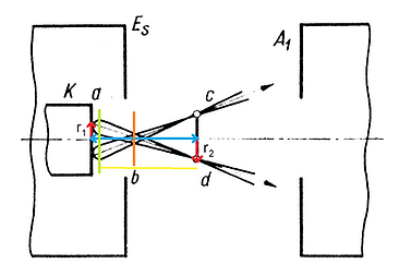
Alpha may be determined by an aperture, maybe by an electric field, everyone says something else. In my eyes there's no reliable information to go by on this one. If you were to do simulations, however, Mulak approximates the actual angle (so not the asymptote) to be from -90 to 90 degrees with respect to the normal of the cathode. Let's zoom in on the gun itself:

Yeah... tackling this subject as linearly as I want to is not feasible, you can see everything is an interplay of many different variables but alas. K is the cathode, Es is the grid, A1 is the first anode. If I could tell you how long it took for me to figure out the mathematics, you'd get demotivated to try to dive deeper into the material so I won't. One will see immediately, we are technically trying to focus two properties of the beam at once. Not only do we see the electrons diverge from every single point of the cathode which we can converge with the help of our anode with crossovers signified c and d, also due to the finite diameter of the active region of the cathode we get a convergent beam with the crossover signified with the orange bar.
I hope you can imagine, trying to focus both into a fine point is incredibly difficult, it is also not always really necessary. Picture tubes do not need to project a fine point, here you want to optimize the used surface area of the cathode to produce a good beam current and therefore a higher light output. Engineers often used to opt to do nothing with the inherent divergence of the exiting electrons, but instead tried to focus the "image (r1)" of the cathode into a fine dot.
Electron microscopes do not really need as high of a beam current, but care more about creating a neat parallel coherent bundle of electrons which allows to be focused into a very fine area. In that case, it is more interesting to ditch the flat cathode and opt for a hairpin such that the image is as small as possible. Then one only needs to focus the inherent divergence of the beam which is much easier to deal with.
Anyways, in either case it is interesting to look at the focusing of the inherent divergence of the beam, whether it be a flat cathode or a hairpin. Let's look at the following general lens equation:

This is a formula I managed to verify in Zinchenko's book: Course Lectures Electron Optics. For the initial beam divergence right at the cathode, let's say U1 is the electro-kinetic potential of the electrons in the plane of the object, U2 is the potential of the electrons in the image. Lengths a and b are the length between the image and object and the green virtual lens plane. We are not going to pull anything useful out of this formula either for now, but in this particular case we know U2 >> U1. This effectively means that b by definition is always going to be much larger than a for a system with no magnification, or we result with an incredibly small image compared to the object whenever both lengths are similar. All of these parameters are HIGHLY dependent on the geometry of the gun, and I suppose most of this was determined experimentally through either simulation (with the use of an electrolytic tank, rubber potential membranes, numerical calculations through computers etc), or by real-life tests.
We do not need to discuss the convergence due to the active area of the cathode, since we are not going to be able to make use of flat cathodes anyways. Besides, the geometry here is in general mostly fully determined by other factors. Generally the distance between the grid and anode does not matter that much, keep it close, but not so close you risk arcing. You want to put the cathode as close to the opening of the grid's aperture in the same order as the diameter of this aperture.
-----GRID-----
Enough about cathodes, I dropped the word "grid" a couple times already. The grid in an electron gun often serves the same function with a different purpose. In a gun that needs high resolving power (electron microscope), we often use a hairpin shaped cathode. In a gun that needs a high beam current (picture tubes), we use a flat cathode. The grid helps us select the size of the area of the cathode which is used to draw electrons of. You can imagine, the larger the surface area the more electrons get drawn into the gun assembly, the higher the beam current, but the wider the beam (thus for a CRT a higher brightness, and for a microscope, probably worse resolving power). Note that, with a flat cathode, this modulation effect is relatively linear, whilst with an electron microscope, since the emitting surface is a needle shape, there's more of a pinch-off going on. This is mostly because an electron microscope does not really need to automatically modulate the beam intensity, whilst a picture tube does. In an electron microscope we refer to this element as a Wehnelt grid, in picture tubes it is often called a modulation grid.
Interplay between grid and anode
So how does the grid help selecting the area size? Let me show you:

Here we can see four instances of a cathode-grid-anode assembly from top to bottom, otherwise known as a triode gun (quite popular in electron microscopes and vidicons, but ancient technology when it comes to CRTs). The cathode is set as a reference (0), the grid has a varying negative potential, and the anode a fixed positive one (100). Drawn between the elements we can see equipotential lines. Yes, we are dealing with free electrons in a vacuum, so we can generate "voltages" or potentials in the aether between these elements. These equipotential lines show the line/area in free-space with a fixed potential induced by the conductive elements.
Keep in mind, these electrons leave the cathodes surface with very little kinetic energy. Electrons are negatively charged, so if they're met with an electric field ever more decreasing in potential, these electrons get repelled! The images really drive home the importance of the equipotential line with a value of 0 volts. This one is namely the same as that of the cathode. The closer this line is to the cathode, the smaller the hurdle is the grid produces, so the more electrons will pass through. In the first block, the grid is nearly invisible to the electrons coming off the cathode, the potential difference induced by the positive anode dominates the entire system, pulling hard on all electrons that shoot out of the region directly visible through the grid. We have a high emission.
In progressive blocks, we see that the grid becomes more and more negative. The 0-line moves away more and more from the cathode, meaning the effective area the electrons can overcome the repelling force of the grid, dk, decreases. Eventually, this 0 line is pulled fully away from the cathode. This is called pinch off. No more electron has enough kinetic energy to overcome the grid's field, the beam current is 0 A.
As a thought exercise, think about how the behaviour would be with a hairpin shaped cathode. Besides this, keep in mind this situation works with arbitrary numbers and geometry, it is just an example.
Grid Electron Optics
For the lack of a better subtitle...
What we not have discussed yet is the variable ds in the picture. This is the first "aperture" in the system. An aperture is a thin walled hole which blocks out unwanted particles/photons in an optical system, and helps with sharpening bundles and reducing bundle diameters at the cost of light intensity/effective beam current. In a hairpin shaped cathode, this aperture does not play an incredibly big role, but for a flat cathode it does completely define the active emitting area. The size of this aperture is somewhere in the order of 0,1 - 1 mm and should be carefully chosen depending on the use case.
Thus, you should think very carefully what in your system determines dk for the continuation of your calculations. For a flat cathode, the largest possible value would be the size of the aperture. For a hairpin, it would be about the diameter of the tip. You can see in electron microscopes, especially the ones with incredible resolving power, these hairpins are not made from a thin tungsten wire anymore, but they heat up drawn out crystals (LaB6 / CeB6) with a tip the width of a couple atoms! Some microscopes move from thermionic emission to field emission, but that's beyond the scope of our project. If you manage to get your hands on a LaB6 or CeB6 source, it should take little modification to get it going however, and it will greatly increase the resolving power of your microscope if you did a good job on the optics. Savour owning one, be gentle with it, for the hobbyist, they're irreplaceable!
Let's have a look at the following situation, again, a flat cathode, it's a picture tube:

Here we can see an example of a full tetrode gun. This is a bit of a testament of the age of the book. At the time, around the 1960s, this was the most popular iteration of the electron gun in picture tubes, but I deliberately chose this for its versatility. It uses two separate anodes, one to help peeling off the electrons from the cathode, the other to do the bulk of the acceleration.
The thing is, we're hobbyists, so whether we are trying to make our own picture tube or electron microscope... which sounds super ambitious but we have to start somewhere... It is important to acknowledge our limitations for now. Before this system, you could opt for a triode gun, after this one came tetrode guns with automatic focusing. Triode guns can be a hassle and need external magnetic focusing coils, not unrealistic, but not convenient to build. Tetrode guns with automatic focusing were needed mostly because the transition from monochrome to colour picture tubes was made, and it was incredibly important the gun was made robust against fluctuations in the acceleration potential since the guns had to perfectly line up with a shadow mask.
I doubt for now hobbyists are looking to manufacture colour picture tubes from scratch since no serious successful attempt has been documented of a good working monochrome one. Looking at hobby SEMs and TEMs, the biggest issue are the restraints regarding the vacuum chamber. It is unfeasible to get a custom one made for many, it is easiest to get a sufficiently large chamber, and fit all optics within the vacuum rather, compared to commercial microscopes with electromagnetic deflection where they have the liberty to wrap the coils around a chamber the shape of a very narrow channel. If electrostatic focusing is our big restraint, then this topology allows us to remove the condenser lens, and have the two anodes perform this function. This tetrode gun is therefore the only one I will discuss. If you want to change the design and try something else, I think this is a good gun to start adapting into what you need.
In a triode gun, the potential between the grid and cathode is usually much bigger than in a tetrode gun. The grid is always negatively biased with respect to the cathode, but it may be helpful to build a slightly bipolar supply by about 10% of the negative range that can drive the grid positive to ensure full cutoff. For a triode gun, often this voltage ranges between -500 and 50 volts or so, and for a tetrode gun maybe -100 to 10 volts. Also keep in mind that whenever the supply goes positive, electrons are being accelerated, so energy is induced into the system. The positive range needs to be able to supply current, this is not necessary for the negative part.
-----ANODE-----
Projections and Magnifications..
What we see in the optical analog are two lenses. This geometry is brilliant as it technically makes the resolving power insensitive to the active area on the cathode. Ideal for television sets where you do not want the beam diameter to change depending on the modulation, but we are restrained to a hairpin so this model does not really apply to us.
The element in the picture with a potential of a "1000V", the first anode, is sometimes also referred to as the focusing anode. We can drive this anode with a resistive divider from the main acceleration potential, and is often between 1/3rd and 1/10 of the main acceleration potential with respect to the cathode. The beauty of this anode is that we can essentially make good adjustments to the focal length l2' of the immersion lens formed by the cathode and focusing anode. This is another reason why I highly recommend the use of a tetrode gun. We do not really need to know what the electrons do in the gun, through the incorporation of an aperture, we can make the system more predictable.
How? I am going to make a gross simplification and generalization here. We can assume that the first crossover in our system will happen somewhere inside the focusing anode. If we look at existing gun geometries, the proportions of these elements all seem to be quite similar. If we simply make the distance from the accelerating anode until the next element (an aperture) incredibly long, and measure the beam current on this aperture, we can adjust the potential resulting in the crossover being moved back and forth, we essentially generated a predictable divergence of the beam!

Now C is the cathode, G the grid, A1 the focusing anode and A2 the accelerating anode. Let's say now, D is the aperture held at the accelerating anode's potential, distance l away from the centre of the focusing anode. The aperture has diameter phi. The formula listed in the figure then can calculate the beam divergence, theta as long as the beam is wide enough to hit the sides of the aperture. The original beam divergence is not important as we can see in cases 1 and 2, because the aperture decides for us now what this divergence is at the cost of beam intensity.
Here we use an approximate sign. We assumed for the focal point to be somewhere in the middle of the focusing anode, but this does not necessarily have to be the case. Since the physical length of the focusing anode is much smaller than length l, this is a good estimation nevertheless.
But HOW do we determine whether we are actually hitting the aperture? It could be that our beam diameter is way too small. This is easy, since rather than directly hooking up our aperture to the accelerating potential, we may put a microampère meter between there. The impedance of such a meter is sufficiently low the potential developed on the aperture by the beam current is negligible compared to the accelerating potential. Simply adjust the focusing potential until you see the needle of the meter deflect from 0uA. You can even use this aperture to align the beam with a quadrupole, but this is not within the scope of this page.
The energy of the electrons is that of the accelerating potential, which is often somewhere between 1kV for a small oscilloscope CRT to 150kV for a giant Transmitting Electron Microscope (TEM).
-----CONDENSER LENS-----
From here on, we are not as much limited by geometry anymore and we can start using math. We have a beam divergence, we can identify about where our first crossover starts, and we have electrons all with about the same energy. The only problem now is that we have a diverging beam probably resulting in a uselessly large spot size. We want a converging beam, thus, we need to add a condenser lens.
There's many many many different lens topologies out there, the electron optics connaisseur I am (not) has the largest preference for 3-element lenses. These lenses namely consist out of 3 cylinders/apertures, where the outer two are tied together to the same potential. We can actually tie these together to the accelerating potential, meaning that we do not change the energy of the electrons whilst still properly deflecting them. This trick is most often used in colour CRT guns with automatic focusing.
Another benefit of these lenses is they're incredibly well documented.