
Finished: 02-11-2024
DISPLAY V1.0
A high bandwidth x-y radar display
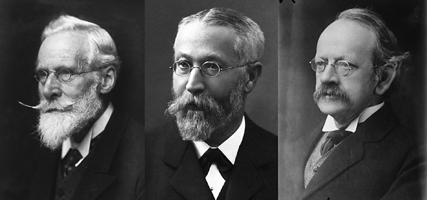
One of the largest innovations within the domain of electronics was the invention of a means to display a two variables against each other. Whilst early methods often used plotters where by default one of the axes represented time and was often kept at a constant pace, it is the Cathode Ray Tube or CRT that really changed the world of measurement equipment, and later, media distribution. Since the evolution of this device was relatively gradual and it took a couple decades to find a proper implementation of the knowledge. I do not plan to go into detail about electron guns in this article since I will design a super fancy one later on with you all! As for the deflection part: if you want a further read, then I highly recommend referencing William Crookes, being the founding father of pulling electrons off a conductor into a free partial vacuum, Ferdinand Braun, for innovations introducing a homogeneous phosphorus screen and optimizing tube geometry for deflection and Sir Joseph John Thomson, for introducing electrostatic deflection plates to the equation. Obviously these aren't the only people who made massive contributions, but simply the best documented ones.
Motivation
For my main project, the design of a scanning electron microscope, obviously some kind of screen is needed. The goal is to generate pretty pictures after all! That's where this project is all about. I lucked out and managed to buy an old Japanese ship radar that came from a fisher boat with the idea to reuse it as a monitor for the project, but I quickly found out this was not going to be an easy project. With a high voltage supply sparking violently and smelling like ozone, a very low bandwidth yoke made of electrical steel, the lack of deflection amplifiers, needing a million different supply voltages, the assembly being generally way too heavy and large, and most importantly, the severe lack of documentation, I decided to take the easy route meaning I will do the electronics design of the monitor myself. With the design of a new highly stable high voltage power supply, a high bandwidth video amplifier, and set of very low impedance deflection coils, we can ultimately build a big high bandwidth x-y monitor which is useful for all kinds of other projects too!
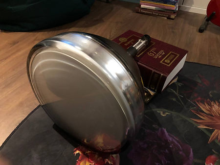
I completely stripped the unit carefully, pulled out the CRT, checked the filament for continuity (it would be a shame to design a monitor for a dead picture tube), checked the phosphorus coating for any burn-in, and carefully looked at where all the wires from the tube socket went to so I can reference part of the circuit to determine the pin-out of the tube and deduce what voltages the CRT might have operated on.

Constructing a 'datasheet'
Now, the next step would obviously to Google a datasheet and get to work. The problem is, there is absolutely no documentation of this picture tube available. Same for the entire radar unit in general to potentially derive voltages and operating points from. The CRT was made by Mitsubishi so my first instinct was to maybe send an email with the idea they might still have documentation available in their archives. Radars, even these old ones, still get repaired or rebuilt as system upgrades may be too expensive, but rather than a "I'm sorry, we can not help you with your request", they just didn't bother to reply at all. This means we have to get creative.
What we do know already, is that this tube has a long persistence type phosphorus since it is a radar screen. What we also already can deduce are variables strictly dependent on the geometry of the tube. The screen diameter is for instance roughly 30 cm. Roughly knowing the centre-point of the position of the yoke, looking at the side profile allows us to determine the deflection angle is about 50-60 degrees (which initially might sound incredibly dated for a tube produced in the mid 70s, but I see this as a benefit! We have the advantage of a relatively modern phosphorus coating and gun assembly, whilst we also don't need as large of a magnetic field to get good deflection compared to that of a television from the same era with a deflection angle of above a 100 degrees, allowing for less complicated deflection amplifiers. The screen has a larger radius than the distance from the deflection point to the screen, meaning we will have to deal magnetically correcting for distortions.


We can now take a closer look to the gun assembly:
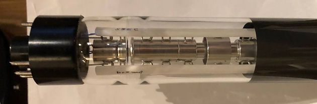
This is probably one of the last iterations when it comes to electron guns specifically for a monochrome screen. The dead giveaway of the style of gun is the lens towards the left consisting out of two small cylinders wrapped around by the big one. Here we speak of a "tetrode gun with automatic focussing":
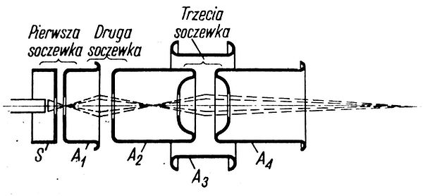
I refuse to go into detail here because there will be an article that goes very in depth on electron optics but to briefly summarize, this is a gun topology which is relatively robust against fluctuations in the accelerating potential (10-20 kV), whilst the addition of the lens (in the image consisting out of A2, A3, and A4) allows for focusing to be done at a relatively low potential (0,5-1 kV). This means the focusing can be done with a separate potential, allowing for a lower power supply for the acceleration potential. Also, we can even make an active focus control where we can compensate for any distortions in focusing due to the flat nature of the screen!
Anodes 2 and 4 are almost always tied together internally and held at acceleration potential. Anode 4 is usually also connected to the aquadag coating inside the CRT to keep a homogeneous electric field for the electrons to fly through. This all means there are 7 connections in total to be made to get the CRT functioning (you could've deduced this from counting the connections on the tube but we now removed all the guess work). Namely:
-
2 connections for the filament supply
-
1 connection for the cathode
-
1 connection for the modulation grid (S)
-
1 connection for the screen grid (A1)
-
1 connection for the accelerating anode (A2 + A4)
-
1 connection for the focusing anode (A3)
Filament supply
There's one piece of wisdom I want to share that goes for making any tube operational without a proper datasheet: DETERMINE THE FILAMENT VOLTAGE FIRST! If you are going to screw up, you might as well do it early in the process. This is namely quite a high risk procedure!
Obviously, if you have fancy equipment like a spectrometer and a reference like a good gas discharge lamp, you probably already also have the knowledge to deduce the filament temperature referencing black body radiation (we will be doing something similar at some point in the future), knowing the temperature should be somewhere between 1000 K and 2500 K depending on the type of filament used in the tube.
An easier method is using a bit of common sense. In American devices, due to a low mains voltage, tube filaments were often easily chained in series and attached directly to the grid. This was convenient since many (cheaper) radios from the time often did not need a mains transformer to power the device. Current regulation could be done by a baretter to account for fluctuations in the grid, it was an excellent method to bring tech to the masses at lower cost. Therefore, the current rating of filaments became incredibly important to be accurate, resulting in the bulk of the tubes having a rating of 150 mA, 300 mA, or 600 mA.
In Europe, we thought this was scary, because there is no galvanic separation with the grid. It could be the case any metal bit sticking out of your radio was live, meaning you could get a nasty shock. Transformer less (or well... not speaking about an output transformer) radios were rare and were mostly produced during WWII due to scarcity of materials. We opted for using galvanic separation, and operating all filaments in parallel. Suddenly the current is not the leading variable in your design anymore, but the filament voltage is! Which lead to a rough standardization of filament voltage of 6,3 V or 12,6 V (often provided with a centre-tap to decide what voltage to run the filament on in your system).
Now, in most cases, American tubes had European equivalents, European tubes had American equivalents (I include ex-Warsaw-pact countries as well with Europe by the way), we all could reference each other's schematics, basically leading to BOTH filament voltages AND currents often falling within the ranges discussed above in the "modern" days of the tube-era. And this is incredibly convenient, since the I-V relationship of a hot wire is NOT linear, all you have to do is hook up your filament to a variable supply, measure the potential across- and current through the filament, eventually you will end up with the two variables perfectly matching up with the literature described above.
NOW I want to be incredibly clear. NEVER DO THIS UNLESS YOU CAN'T POSSIBLY FIND A DATASHEET!!!!!. Google around, find table books, ask on forums, look for schematics that use the same tube, the likelihood of this data being in someone's possession is big! This method is NOT a one-size-fits-all solution, the likelihood of it working is also highly dependent on the time and country of manufacture of the tube. This is a LAST resort method. Besides, the only reason I was confident doing this, was because somewhere down the line in the radar circuitry I found a light bulb in series with the filament which had a voltage rating of 8 V, I had a threshold I was willing to test my tube at. But I got lucky, for me the figures did line up. I found my tube probably comfortably operates on 6,3 V, at 600 mA.
Now are these tubes often manufactured with a tolerance of around +/- 10%. Since I will have a mains regulator (a motorized variac) between my microscope and the grid, to preserve the filament life I can comfortably de-rate it to 6V, at 570 mA or slightly below that. This is actually big point of discussion on the internet and there is a large amount of conflicting information (mostly from the audiophile community) where people pull the wildest conclusions and thinking up incredible theories. Truth to the matter is, the amount of free electrons due to thermionic emission is the only variable really dependent of the filament voltage besides lifetime, the maximum anode current is limited due to a constant being the tube geometry. Oftentimes, the temperature of the filament is chosen such that within the given tolerances, there is an abundance of available free electrons with respect to the maximum anode current, resulting in a negligible change in operation of the tube. Only when you go outside this band, at a lower temperature there won't be enough electrons and your tube will behave non-linear at lower anode currents, and at higher temperatures, the tube won't behave much more differently besides having a significantly lower life expectancy.
The pins for the filament can of course be easily found by checking for continuity with a multi meter. At low temperature/power, this shows up as a near-perfect short.

Accelerating potential (A2)
For the acceleration potential, geometry is not going to help you determine a ballpark value. Here knowing the function of the device is much more important. Do you have a tube with electrostatic deflection? Then it is likely a monochrome screen with a very low acceleration potential. Electrostatic deflection is relatively ineffective and fields are hard to scale, the tube you have is most likely from an oscilloscope (or a very old TV set). Good focusing and resolving power are not important, but linearity and the bandwidth of the deflection are. Depending whether you have flood guns and all that jazz, these tubes usually do not exceed an acceleration voltage of 5 kV, where for most 2 kV is already more than sufficient.
When you know your tube has magnetic deflection (which is often paired with a relatively narrow neck compared to that of an oscilloscope CRT), and you only see ONE electron gun in the gun assembly, this tube is most likely monochrome. Whilst proper focusing of the electron beam over a large deflection is easier with a higher acceleration voltage, there is a limit mostly due to the resolving power of the phosphorus. This means the majority of these tubes range from around 5 kV to 15 kV.
If you see three guns, then it is most likely a colour picture tube. Since now you have three guns and a shadow mask blocking part of the electron beam before it hits the phosphorus layer, the philosophy is to just go as high as possible with the acceleration voltage before you start generating more bremsstrahlung (x-rays) than you can actually shield the viewer from. These tubes often operate somehwere between 15 kV to 30 kV.
Finally, there is a special animal in the CRT world that puts these figures to shame, which are projection tubes. These are very long tubes, often with liquid cooled phosphorus, with a small screen diameter that needs to somehow pump out an absolutely ginormous amount of light resulting in extraordinarily high beam currents and voltages. These are always monochrome, since for colour systems, you simply get three of them with a filter in front of the screen. As these are not direct-sight screens, and reflect their light off a parabolic mirror, these tubes are easy to shield properly. These go from 30 kV to some as high as 80 kV, with beam currents in the order of milliamps! The amount of chemistry and engineering that needed to go into these tubes for the phosphorus compounds not to denature and introduce spark catchers to survive electrical breakdown can't go without mention. It's a tube that deserves a spot in anyone's collection.
Thus, what should I use for my tube then? It is easy to make the mistake that the main accelerating potential is mostly dependent on the creepage distance within the tube, but since it is in a vacuum, there is no set-in-stone calculation you can do to determine this. Arcing isn't usually caused by creepage, but due to electrical breakthrough due to field amplification at triple-points (conductor/insulator/vacuum). I'd say you can probably get away with simply looking at the measurements of your tube, compare it to a couple other ones you can find the datasheet of with a similar electron gun and screen diameter, take the average acceleration voltage +/- 1 kV, and call it a day.
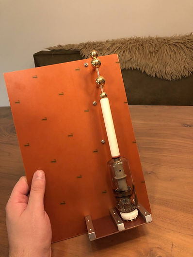
I happen to have another metric to go by, the radar manufacturer actually used a voltage tripler cast in clear silicone:

Since a tripler is essentially a 3-stage Greinacher (or Cockcroft–Walton), we can easily deduce from the capacitor rating what voltage would've been produced at the output. These capacitors are 6 kV, all identical, meaning at the input, a max voltage of 6 kV p-p, is allowed. The amplitude of the input signal therefore would've been max 3 kV, meaning at the output there would've been an (unloaded) DC voltage of 9 kV. These capacitors were likely to be derated with 10-20%, meaning we end up with an predicted acceleration voltage between 7-8 kV.
I wish I could've used the datasheets to see the voltage ratings of the diodes, but like the rest of this stupid radar, obviously also the diodes aren't documented (yet).
Now, we can also try to compare our CRT to some other ones of a similar screen diameter with a tetrode gun referencing a vacuum tube table book. The most similar picture tubes I managed to find regarding screen diameter and deflection angle were the MW 31-16, 12DP7A, and the 12KP4-A. Let's look at them side-by-side:

Once one takes a closer look to the datasheets, something very interesting can be seen. Firstly note the maximum ratings: they all share the same maximum potential of the anode voltage most likely because we picked three tubes with a very similar geometry and electron gun construction. I think we can safely say, our tube has the same absolute max rating of 11 kV. Now, what's maybe more interesting is the strong variation in anode voltage for typical operating conditions. Sylvania down-rates their picture tube all the way down at 4 kV. Further in the datasheet (found at the download page), it is stated from this point there's loss in "brilliance and definition", meaning technically this may be seen as an absolute minimum rating. General Electric states their tube loses "brightness and focus quality" below 9 kV. This tube is marketed to be used in high-ambient-light conditions, so it makes sense the manufacturer wants the engineer to operate the tube at a high anode voltage to fulfill their promises. Philips does not care about marketing and immediately plays open cards, the datasheet provides us with theory and information on how to set up the tube for the best picture quality, and tell us exactly what beam current to expect. They pick the middle ground somewhere between 7 - 9 kV.
What does this teach us? Anode voltage literally does not matter. We can reason, the higher the voltage, the higher the current, the higher the light intensity. The tube will be used in a lab, meaning good ambient lighting, but not necessarily a summer sun causing a ton of glare on the screen. Therefore I think the approximation with the voltage tripler is quite accurate: we operate the tube somewhere between 7 - 8 kV. According to Philips' datasheet we can expect a beam current around 300 uA. I'm going to be very conservative here, I do not have the space to experiment with different high voltage power supplies, hence I will design the anode supply at something like 800 uA. This also safeguards me in the future, may the tube burn out, this will never be a restraint.
Screen grid (A1) and focusing anode (A3)
Now my reasoning will go further out the window, since to determine the voltages for the next elements, if we do not know exactly the geometry of the elements and run simulations, whether it be through the use of an electrolytic tank, resistor networks or the computer, we are basically left to determine the final potentials experimentally.
Now I'm lucky, since my CRT came from a radar unit which I happen to have in my possession. The power supply for the first anode and focusing anode were conveniently located on the same assembly, and there was some limited silk-screening I can go by to determine what originally would've been put out by this module. Let's first look what Philips, Sylvania, and General Electric have to say. It's quite a diverse bunch of tubes in the end, the values seem to lay between 160 - 250 V. All of these tubes use magnetic focusing however so nothing relevant can be found in the datasheets. The board delivering both the supply voltages looks like this:
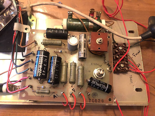
I do not plan to use this board anyways, this unit was initially built to power the CRT from 18 volts so it uses a nasty boost converter. Instead of shielding interference, I prefer not to create more nasty signals than I need to, the power supply will therefore be linear. Besides, I'd have to build a second power supply to go from mains to 18 volts, I might as well do this conversion directly to the appropriate anode voltage.
Now, they did not go wild on the silkscreen, but I have to say they threw us a bone by at least identifying one voltage coming off the board through a red wire to the tube socket, namely 530 V. In the assembly, this wire goes to tie strip labeled "AV". This is actually quite far from our prediction, but I have to mention clearly that the electron guns in the example datasheets are not fully of the same type. These are namely tetrode guns for electromagnetic focusing. Whilst both systems are capable of properly illuminating a sharp picture onto the screen, the focusing mechanism differs inherently. Whenever we look at some specifications for colour television tubes where automatic focusing IS used, the potential of the screen grid varies roughly from 1/40th to 1/20th of the accelerating voltage. In that case, our 530 V starts to make more sense.
Now it happens to be the case for a second red wire going to the tube socket, labelled "Eb1" next to that terminal. This terminal is quite literally directly connected to the wiper of a potentiometer across 530 V and ground, labelled "FV" on the tie strip. Now, recall I was talking about a "tetrode gun with automatic focussing". With this topology, it is about as standard as it gets to hook the first anode up to a fixed potential, whilst having the focus voltage fully variable between cathode ground and some arbitrary "low" voltage in comparison with the accelerating voltage. Since these accelerating potentials are positive compared to the cathode, they do not need to supply a lot of current. This makes life incredibly easy, we only need to somewhat regulate out fluctuations in the mains voltage, but we can achieve our desire potentials accurately through a resistive divider. The potentiometer for the focusing potential is an entire whopping megaohm! Dynamic focusing can be done by adding a transistor in the voltage divider of the focus control, and should be made dependent of the distance from the centre to the beam to the centre of the screen. This ensures for proper focus all over the screen rather than it just being tuned in one area (these artifacts are caused due to the radius of the curvature of the screen being much bigger than the distance from the deflection coil to the screen, meaning a different focal length is needed of the lens-system the further you go out from the centre.
These voltages do scale with the main accelerating voltage of A2. This means, may my estimation have been high, I might not have enough headroom with a 530 V power supply. I'll take anything around 800 V , mostly depending on whatever suitable transformer I have laying around, and divide it down appropriately for a quality picture on my tube. This also gives me enough headroom to add necessary bias circuitry at the cathode for the video modulation.
Modulation grid (S) and cathode
This leaves us with our final two ingredients. Our modulation grid and the cathode. Now, you may say, "but Mareijn, you measure every voltage above in reference WITH RESPECT TO the cathode", to which I say yes, that's true, bet allow me to explain to you how this assembly works first okay?
In the early pioneering days with "cathode rays" when people still used cold cathodes, scientists had fairly little control on WHERE the electron emission happened at the cathode. This resulted in a very large and uncontrolled emitting-site which was hard to focus into a fine bundle to produce a sharp dot. Thus, if there were a way to discriminate electrons where only ones from a small area are accelerated whilst the other ones are kept back, we inherently create a narrower bundle from the source, resulting in a sharper projection with the same electron optics. Arthur Wehnelt was the first (or at least most prominent) person to add a third critical element to the electron gun (with the two other elements being the cathode and anode). He namely placed a small aperture right after the cathode with a negative potential. But why? you may ask. We want to accelerate our negatively charged electrons with a positive potential so we can build up a lot of energy to create a ton of light! Let me help you visualize:
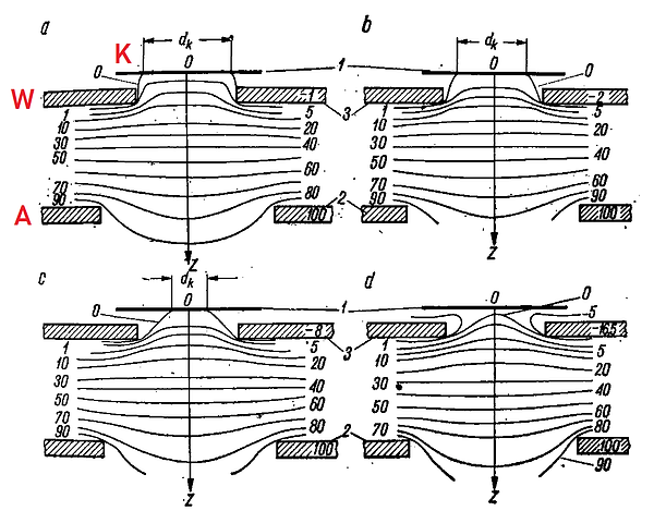
Here I helped you out and labelled the elements K = cathode, W = wehnelt "cylinder", and A = anode. The lines you see here are called "equipotential" lines, and are in this case normalized from a scale from 0 to a 100. If this looks horribly abstract to you, just pretend you are a football player, standing at the cathode. These equipotential lines resemble the depth of a valley in the ground, the higher the value, the deeper the valley, the lower the number, the higher the elevation (I know, super counter intuitive). Now we place two mountains in front of you, one a bit to the left, the other a bit to the right. You have a ball, the electron, but only a limited kicking force. If the mountains have a height of 0 (a wehnelt cylinder with a potential of 0 V), then it doesn't matter how hard you kick or where you stand, all balls will roll down the valley. But the higher we raise these mountains, the more precisely you have to kick the ball in-between those mountains, and the harder you have to kick to overcome the hurdle for the ball to roll down the valley. This means that only precisely aimed balls between the mountains, and strong shots are discriminated from the less accurate shots. Now, of course we can raise these mountains even further such that you simply can't kick it hard enough over the mountain ridge for it to end up rolling down the valley. This is called the 'pinch off', no more electron will make it out of the system.
If we go back to the abstract world, this inherently means that we modulate the spot size by changing the potential between the cathode and the wehnelt cylinder. The more negative we make the wehnelt compared to the cathode, the less electrons make it through and the more get repelled backwards. Only the ones fast enough that originate from the centre (of which the active diameter of the area in the image is called "dk") will go through the aperture until the wehnelt gets too negative, keeping all electrons from going through.
Now, I hope you can see now by varying the voltage applied to the Wehnelt, we can change the amount of electrons making it through, changing the beam current which changes the light intensity of the spot. But a potential is always measured between two spots, we now speak relative of the cathode, but let's say if we would hook our wehnelt cylinder to ground, then we can achieve the exact same effect by raising the cathode voltage as if we were lowering the wehnelt voltage in the previous example! Here we speak of grid-modulation, and cathode modulation, or negative and positive modulation since the video signal would be inverted!
Now, there are various reasons one may opt for either type of modulation, but I will keep it easy for you all. My preference goes out to grid-modulation since cathode modulation also affects the focus of the beam. Not only would we change the beam intensity, we actively fluctuate the voltage relative to the accelerating anode! Since we are going to use a tube as a video amplifier to drive the grid, we are inherently stuck with our video signal superposed onto a positive DC voltage. This means we need to organize an even more positive potential for the cathode. If we were to use an EF80 as a video amplifier (which we will), and a power supply of 200 V, we could directly use the power supply for the EF80 whilst hooking the cathode up to a resistive divider including a high voltage NPN transistor to ground. If we were to power the transistor by default, the resistive divider can be chosen such that the cathode and grid are operating in their workable range (say the modulation voltage range is -20 to -50 V with respect to the cathode), say a 160 V, then the anode voltage of the EF80 should fluctuate between 110 and 140 V. Now, to do blanking seperately, when we switch off the NPN transistor, the divider will agressively pull the cathode voltage up to our 200 V supply, meaning there will be minimally 60 V, and maximally 90 V potential difference between the grid and the cathode, definitely forcing the system into pinch-off, no matter what the video signal looks like. I have no idea what voltage the grid should operate at compared to the cathode, but it should not be more than a 100 volts looking at the example datasheets. Let's take a 250 V supply for now, operate the cathode around 180 V, and the grid between 100 - 160 V and tweak from there!
Pin-out
Now we figured out how we are going to fire up this tube, what's left is to determine which connection is which. When you're lucky, and you have a tube with a glass base, you can simply look inside the envelope and determine what elements the pins are connected to. When you're unlucky like me, you have a plastic base that obscures your view, and if you're even unluckier than me, you also have to deal with a getter obscuring your view further.
Now, my glass envelope only has 10 connections (without the accelerating anodes terminal of course) at the base, the socket itself is meant for a 12 pin connector of which only 6 are populated. The likelihood of there being any pins crossing in the socket are slim but not necessarily impossible. Let's first take an educated guess, then we compare to literature. My observations looked as follows:
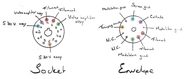
Now, for the 12 pin socket, I simply looked at what assys the wires went through during dismantling of the radar screen. We determined above, the video amplifier most likely takes care of the cathode and modulating grid, the 530 V assy takes care of the screen grid and focusing anode, the filament we measured first and determined what two pins had continuity. On the left, you can see the 10 pin glass base of the tube, here we can derive the order or the electrodes. The modulation grid was tied to 3 separate feed-throughs, but it becomes apparent that the cathode, screen grid and focusing anode terminals are is positioned in the counter-clockwise direction of one-another. I think we can therefore safely say, that pin 2 is the modulation grid, pin 6 is the focusing anode, pin 10 is the screen grid and pin 11 is the cathode.
This all is not that surprising, whenever we reference the literature, the majority of pin-outs are actually in this order:

Here pin-outs 1, and 7-12 share the same order as our estimation. Interesting is pin-out 6, where engineers decided to feed all attachments to the modulation grid through the socket. For 5, the order is most likely the same but they fed through a different attachment point of the modulation grid, and 2 and 3 simply moved the screen grid around. The pin-out of 4 is simply 180 degrees rotated. There is definitely some established standard going on. Who knows all of these companies used the same jig to align the electrodes of the filament, cathode and modulation grid, or the design was generally done externally, but it is a very safe bet to say my prediction is correct for firing up the CRT.
Also, note that pin-out 2 is the only one here that resembles the identical gun we are dealing with since we see anodes 2, 4, and 5 are connected to the same pin whilst anode 3 is given to the engineer to deal with. This happens to be the automatic focusing unit shown schematically at the beginning of the page. Anode 5 then resembles the aquadag coating inside the picture tube. As an example, look at one CRT that uses this pin-out, such as the AW 43-88, and see if you can spot all elements:
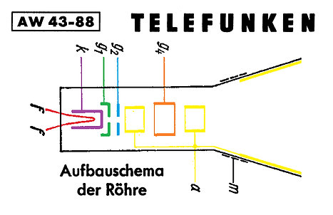
To briefly clarify, this tube's physical geometry is way too different from ours to pull any useful figures from. Also, "m" is not an electrode, it is a coating on the outside of the CRT which the engineer is supposed to hook up to ground. The aquadag coating on the inside is at high potential and the glass acts as a dielectric, meaning this actually serves as a capacitor to help smoothing out the ripple in the power supply of the accelerating potential. This is the structure that tends to arc over when the rubber anode cup does not make a good seal with the glass anymore, and which retains charge after powering own the device. Generally, the outside of the tube is grounded and all high voltage connections are shielded behind rubber in commercial devices which renders a CRT technically quite harmless and safe to touch, even during operation, but once you go ahead and take it apart, exposing those connections, it is good practice to discharge the tube through a resistor by "shorting" the anode to ground to prevent a nasty (often fatal) shock.
My work practice here is often to put a picture frame in prominent view with a loved one, it makes a you bit extra careful and less over-confident when working with a CRT. In the end, you won't be the one suffering, but your loved ones will.
Summary
Now, we actually have data to base a reliable design on rather than carelessly screwing around and potentially sinking a lot of energy into something that's barely going to work. This kind of research looks like it takes a lot of time, but for me documenting it on this page took waaaaay longer than digging through the actual data!
In the end, we established together, we need to build four subsystems to power up our picture tube (without deflection circuitry!).
-
We need a fixed regulated high voltage power supply for the accelerating potential, let's pick 7 kV, 800 uA
-
Then we need to build a fixed supply at around 800 V at negligible current for the resistive divider to supply the screen grid's potential and a relatively low bandwidth option to modulate the voltage for the focus.
-
We also need a filament supply of 6 V, 570 mA. This one may be DC, I will opt for an AC supply however. This mainly because it allows us to keep the topology simple, whilst using parts that fail as an open circuit rather than a short. Every part in our system can handle excessive voltages above our established operation potentials, but the filament is not as tolerant!
-
And finally, we need a video-capable power supply for the cathode and modulation of the grid. The modulation grid actually does need to supply current since it is negative with respect to the cathode, but if we design our circuit around a popular video modulating tube, I am sure we will meet the current requirements automatically. For this we take 250 V
7 kV REGULATED SUPPLY
Shunts 'n Ballasts
Over the years, I've come up with a hand full of high voltage supply topologies that were ideally meant to be used as the main accelerating potential in my electron microscope project. Some inspired by state-of-the art regulation methods being used in modern supplies, others simply by scaling linear supplies using an obscene amount of cascodes to build HV capable active regulators. Then in like an hour, I decided to throw a couple years of designing and prototyping out of the window because this problem was already solved decades ago in the most elegant solution ever, but was lost in time after the lack of a need of highly stable HV supplies in consumer products. Is it efficient? No. But it does have excellent regulation with a very little amount of parts, and that is what we're after.
I am mostly talking about shunt regulators. Back in the early days of colour television, an incredibly stable acceleration potential was needed to achieve properly converging and deflecting the beams onto a shadow mask. A bit of distortion in a monochrome display is not problematic, but if you are dealing with this shadow mask, you get very serious colour artifacts which make the television unwatchable. So, before using the topology in our tube to do automatic focusing with the newly introduced anode, these engineers used guns more sensitive to fluctuations in the accelerating potential. For a couple years, they designed a special type of tube called a "shunt regulator", which essentially models the topology of a CRT's electron gun, but without the focusing elements or a screen, with all the same non-linearities similar to that of a genuine picture tube.
The idea here is, whenever you display a bright picture, the beam current becomes very high, so the power supply gets loaded and starts to sag (due to the output impedance of the supply). Whenever you display a dark image, the beam current is low, the power supply gets loaded less and raises again. This means whenever you focus your beam to be sharp for a bright image, whenever you get a dark image, the potential rises pulling your beam out of focus! Thus, if you'd put your shunt, or ballast, in parallel with your picture tube, what you can do now is whenever your picture tube displays a bright image, you let the ballast "display" a dark one. Whenever the picture tube displays a dark image, you continue loading the power supply by letting your ballast "display" a bright image! The loading now is constant, thus the amount of sag in your power supply is constant, thus your accelerating potential remains constant. Very clever!
"But Mareijn, you DO have autofocusing. Then why would you bother implementing a shunt regulator?" I hear you ask. Well, usually, the accelerating potential is generated by taking the high frequency signal from the fly-back transformer used to generate the signal for the horizontal deflection coil of a television. This is a signal usually in the order of 10's of kHz (depending on the video standard used), meaning you do not need large capacitors to properly smooth out the ripple in your supply. But MY deflection can vary a lot in frequency, since the signals are generated elsewhere. If I build a generator to for a high definition video signal, this may be 50 kHz, if I do radial scanning, it could be as low as 1 Hz, if I use the screen as an analog computer read-out, then this frequency and wave shape may vary continuously through time.
Now, keep also in mind, since in normal televisions and CRT monitors the accelerating voltage is depending on horizontal deflection, even if you were to have a large ripple, your level of de-focus is at least constant across every single line on the same spot. You may get artifacts, but these are synchronized to your image, meaning despite the distortions, you will not end up with a very uneasy looking image. In my case I can not do this kind of syncing as easily, so I want have my ripple synchronized to something I KNOW is the same throughout my system and compensate for externally if needed, being mains voltage. The biggest problem here is, since the frequency is so low, I need quite large capacitors for worse ripple rejection, meaning a ballast with aggressive regulation is necessary to generate an appropriate supply and compensate for the luxuries I am missing out on.
My ballast of choice is also the only one that was really mass-produced in Europe, being the PD510. They're so easy to get your hands on, I found out I actually already happened to own three without recollection of receiving them. The absolute beauty of this tube is how useless it is to the audiophile community. Nobody wants them, maybe you can drive electrostatic loudspeakers with them, but there's next to no literature referencing to use them so they are going below the radar. Even then, most people will opt for known technologies and use output transformers to create the high potential to drive them anyways... but alas, unimportant for us. Even if you were to try using them, they're probably going to fail anyways as-is as they need a special way of mounting to prevent flash-over due to creepage. They're only useful to colour television collectors, but those are very few and far between, meaning the market is over-saturated with both used and NOS ballast tubes for a pinch. On eBay you can get them in packs of 10 for a couple bucks a piece, and I am sure if you ask some local radio/television forum, people can set you up for free!

Here we see this tube can be operated typically at a whopping anode voltage of 25 kV. More than enough for us initially, but whenever we look at the tube geometry, we see it is only about 10 centimeters tall! Our objective is to build a 7 kV regulated supply, we need a resistor to create a significant drop over to help the tube regulate properly, add a pi filter to do the bulk of the ripple rejection, we may end up with give or take 9 kV as the highest potential in our circuit. Even if we were to operate the tube in an unpolluted environment, with a creepage distance of 16mm/kV, we are still 4,4 centimeters short of creating the necessary distance between the cathode and anode connection of the tube. Rats! We all know, we're never going to clean this device on the inside anyways, it should be able to collect a fair amount of dust without breaking down, then we'd still need, say, 20 cm clearance...
This is a strong indication this tube needs a bit of extra attention to use safely and reliably. After a bit of poking around at our local radio/television forum, I was sent an image of the PD510 being used in its natural habitat in a Philips K8 colour television, and through further research I found another example in a PD500 (predecessor) in a Philips K7:
We can see in the pictures above, indeed, rubber insulators are used, similar to an anode cup on a CRT, to prevent flash-over to the cathode. Now am I quite opposed to scrap a historical colour television, or taking an original part a collector could've used to revive their restoration project as a shortcut for one of my own projects. Besides, also these cages date back to the late 60s, early 70s and rubber doesn't last forever anyways. We have to find a good solution so we can make use of these ballasts with commonly available materials so our system is future-proof!
I came up with the following idea:

I can see the sketch is rough, but this is not a matter of exact measurements, I am trying to show you a working principle instead. YOU use what YOU have on hand, I use what I have on hand.
The idea is to elongate the tube and move the anode terminal up enough such that the creepage distance is sufficient. With minor pollution, a good distance would be 20 mm/kV, which at 9 kV would result in a distance of 18 cm. The tube is 10 cm from cathode to anode, so I need an additional 8 cm to operate the tube reliably. As an insulator I bought an alumina tube with an inner diameter that closely fits around the anode terminal. To make a proper isolating connection between the ballast and the alumina tube, I bought a high-temperature o-ring made of VMQ rubber that fits snug around the anode connection. According to the datasheet the tube will get about 200 degrees C, this rubber is technically rated above that but it's a bit on the edge. The rubber is greast up with high temperature dielectric grease meant for sealing sparkplugs.
Then I got a copper tube, 4mm in diameter, with an inner diameter big enough to perfectly slide (and solder) in a spring-loaded pogo-pin. Then I drilled a hole through a brass bead, slid it over the tube and soldered it in place with a heat gun. This bead is used to press the alumina insulator firmly against the ballast whilst all slack in the electrical connection with the anode is taken up by the pogo-pin. To prevent cracking of the insulator, I used a silicone gasket with a hole the same size as the outer diameter of the copper tube to use as cushioning.
Finally I prepared two bigger brass beads, soldering a standoff to the side, and drilling a hole through of 4.2 mm. One of the beads is used as a guide for the copper tube to slide through. The other has M5 threads partially tapped through the hole for a set screw. The tube was cut with a saw such that it would fall about halfway in the threads. With the set screw, we can crush the o-ring between the insulator and ballast such that we have a good insulating seal. Then, a final small bead was drilled through, and threads were tapped such that it could be used to cover the threads of the set screw.
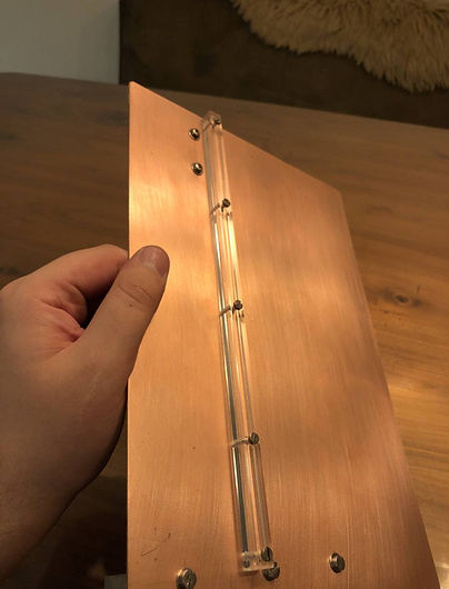
Everything was given a good polish to prevent coronal discharge and field amplification at sharp points since we are dealing with high voltages, and were mounted to a circuit board with an acrylic rod as reinforcement:


"This is all good and fun but I don't have the specialized tools in-house you have" I can hear people utter.
In this example, the only power tools I used was my battery-powered drill and a heat gun for paint removal. The rest can be done manually with files, sand paper, hand taps, a metal saw etc. Get creative! Doing these jobs, accuracy and patience are much more important than the amount of power tools you own. The rest of the circuit board can now be used to build a voltage multiplier, rectifier, filter network and measurement resistor on. The small board has enough space for a simple regulator. The current is inherently limited due to the nature of the high impedance output power supply we need, so we won't have to deal with all that jazz.
VIDEO SUPPLY- & AMPLIFIER
Finally we have to tackle the supply for the modulating grid and the cathode. This may sound intimidating, but we are going to keep it extremely simple with little calculations. We are going to use a high frequency pentode as our video amplifier, but we also will also create a suitable working point for our CRT. This may sound dreadful since we have to design an amplifier that must also be designed for a specific DC operating point, but the modulation of the beam is not a very linear process anyways, so we do not need to really optimize for linearity of the amplifier. As long as it is stable and has reasonable gain, it is suitable for our purposes. The high voltage nature of a tube will also benefit us greatly in the design process we'll see later.
Video modulation
For the choice of tube I want to use the PL83. Why? Because I already happen to own one, but also because these were incredibly popular video amplifier tubes to begin with in early Philips television sets. These can operate on a suitable anode voltage we defined earlier in determining the specs for the CRT.
For video modulation we have absolutely no idea how the modulating grid behaves in our CRT, but if take an average across various picture tubes in one of my table books, it should be biased by default about 30-40 V below the cathode, and the pinch-off potential lies at about 60-100 volts below the cathode. If we deign our amplifier, I think it would be a safe bet to cover the majority of the range effectively, meaning we should put our working point at about 60 V below the cathode potential, whilst also being able to supply a peak-to-peak voltage of 60 V.
So, if we determine now for the pinch-off to be at 60 V, to always guarantee proper pinch-off, we should bias our cathode 60 V or more below the supply voltage such that whenever the video is at max brightness, we can still properly blank the screen. Let's be conservative, and make an adjustable bias round 70 V below our supply voltage of 250 V, meaning we will chose our bias for the cathode at 180 V, meaning we will bias our modulating grid around 120 V.
Enough yapping, let's pull the Va/Ia diagrams from the datasheet:
Since we are dealing with something fancier than a triode, you will often be met with a LOT of different relationships given in the datasheet. The Va/Ia diagram is not necessary for us regarding calculations, but it helps us draw something called a "load line". A tube converts a certain potential difference between the cathode and grid into a current depending on the anode voltage. The load line helps us convert this current into a voltage through the use of introducing an anode resistor.
With this diagram, we can accurately determine a suitable operating point, also known as working point or bias, depending on our design parameters. If we want large gain, we may opt for a relatively horizontal load line mostly at the cost of linearity. Do we want low distortion, this load line needs to be relatively vertical at the cost of efficiency. In this diagram, often a curve is drawn which represents the max power dissipation of the tube, without effective measures, you should keep the entire load line under this curve. With a triode, you would've only received one curve, but I am showing you three. This is because our tube is a pentode. We are dealing with 5 separate elements in our tube namely. The anode, cathode and control grid are the same as that of a triode, but we now get an additional screen grid and a suppressor grid. The screen grid has as function to generate a stable electric accelerating field inside the tube without being disturbed by the changing potential of the anode, this grid can be used to electrically change relationships within the tube. Especially now with this screen grid, electrons smacking into the anode cause secondary electrons to be kicked out of the metal. This can cause ugly artifacts and horrible instabilities in the functioning of this tetrode without very careful biasing and measures against self-oscillations. Therefore the suppressor grid was introduced between the anode and the rest of the tube and tied to ground to segregate between fast moving electrons coming from the cathode which CAN pass through this grid, and slow moving unwanted secondary electrons which CAN NOT pass through this grid, completely removing these artifacts. Note that, when we tie the suppressor to the anode, we can turn a pentode into a tetrode (which is useless), but by tying the screen to the anode we can turn a pentode into a triode. Very fun read, go Google something like "triode operation of a pentode" or "ultralinear pentode". Many cool tricks can be done with this knowledge we won't discuss here.
To get back to our curves, the suppressor is almost always directly tied to the cathode INSIDE the tube. Despite our super cool tube having an external pin for the suppressor, usually all measurements are also done with the suppressor connected to cathode. You CAN use it for different purposes of course, maybe to do mixing, or if you are still suffering from tetrode behaviour, you could bias it more negatively, but this we can look at as an afterthought. A good design shouldn't need this, so we shouldn't aim for this. But the screen grid can, and should play a role in your decision making process when designing an amplifier with a pentode. The potential on the screen grid may drastically change the Ia/Va relationship of your tube, so we should pick the curve that best suits our objective. We don't really need excessively high gain, and we don't really have to aim for efficiency, but we must take into account we do not use decoupling for our amplifier! Usually, we would pick a fixed grid bias and superpose an AC signal on it. We actually do not WANT to do this as we will use a video system without DC restoration. This means we have no safeguard in place against "shorting" out our tube with a positive grid voltage. Worst case scenario, our anode resistor needs to work as a current limit against this problem. During normal operation this should not be a problem, so we just need to make sure during start up/warm up of the power supply, neither our anode resistor nor the tube will be fried. At a short, the tube won't dissipate power, but the max current allowed through the tube is 70 mA according to the datasheet, so at 250 V, we need an anode resistor of U/I = R 250/0,07 = 3,57 kΩ. If we were to use an 3,9 kΩ resistor, calculating back we see our load line has to maximally cross the y-axis at around 64 mA.
Looking at our two diagrams and taking into consideration our relatively low supply voltage, we can see at a screen grid potential of 200 V, around our working point of 120 V there's a weird artifact going on. Besides, the grid curves for 170 V look a bit more equally spaced out than at 200 V. Philips was with this datasheet not as polite as usual, not giving us a power curve. We can easily plot a curve, picking a couple anode voltages, calculating the current at a given max power (9 W), and plotting this ourselves in the graph using the relationship I = P/U:

With red I drew two regions we can't exceed. The curved one is the max anode power that can be dissipated by the tube. The straight one is technically a load line from our maximum supply voltage to the maximum allowed current that can flow through the tube. Now, the orange load line is where I felt goes right through a suitable linear region, but still results in a convenient resistor value. It crosses the y-axis at 50 mA, using ohms law, we can calculate the anode resistor to be U/I = R 250/0,05 = 5,0 kΩ. Whenever the grid is positive and the tube becomes a "short", the power dissipated by the resistor will be P = U*I = 250 * 0,05 = 12,5 W. This is very high, but this is technically not the point we want to operate it. We should therefore consider adding a clipper at the input of the grid to prevent the tube from going into such a horrible bias. Let's first calculate the gain though.
The gain can be calculated with the curve you see on the left. Every now and then you'll have to draw it yourself but it can be easily derived from the right diagram (I intend to write some crash course about this, but if you're planning to do a lot of tube design anyways, I recommend picking up a book. Anything from between the 30's and 60's will be a great resource, my go-to book is actually quite new called "Fundamental Amplifier Techniques with Electron Tubes" by Rudolf Moers. The price is steep, mine was gifted to me by an incredibly kind engineer, but it's a compendium of literally everything you'll ever need to know about linear wide band amplifiers. Super well written, 10/10 would recommend). The gain is nothing more than the output amplitude divided by the input amplitude. Whatever comes out for what you put in. Whenever I put a signal in, peak-to-peak being -2,6 - -3,6 = 1 V, my output voltage swing will be the desired 60 V peak-to-peak. This means we have a whopping gain of -60! (the minus since it is an inverting amplifier). We can use the forward voltage of two silicon diodes, being around 0,6 V, to do the clipping for us. This will maximally allow for an input signal, 1,2 Vpp, or an output signal of 72 Vpp. Around our working point of 120 V, our anode voltage drops to 120 - 72/2 = 84 V, meaning the voltage across the anode resistor will be 250 - 84 = 166 V. Thus, through a resistor of 5,0 kΩ, our current will be 33,2 mA, and the power dissipation will be about 5,5 W. It's up to us to decide what's a more elegant solution, either setting up an adjustable voltage reference with a clipper, or use a beefier anode resistor to help with current limiting. This will mostly heavily depend of what we have laying around, but is not relevant for now.
For a video amplifier, the gain is really high. I recall from the EF80's datasheet, they mentioned anything above a gain of 25 may introduce problems regarding microphonics. Obviously a quick look at each tube reveals a completely different mounting mechanism, we'll see if we need to limit the gain one way or another. Also the screen grid is biased higher than the point of operation of the anode. Despite a lot of controversial literature on the internet, don't listen to them, listen to me, it's okay, it's allowed, you can do it :-).
But can you believe it? A gain of 60, an output amplitude of 60 V peak to peak, and all that in the MHz range, we may have to do some compensation here and there to flatten out the frequency response, but isn't that amazing? With a device that now costs like what? A couple euros for a NOS one, probably even free if you ask some radio enthusiast. Absolutely brilliant. This all with literally a handful of components.
As a final step, we now have to bias the grid. We can see our working point lies at -3,1 V, meaning the grid has to be biased towards that voltage. Now, for the millionth time, our video signal is not AC coupled, therefore it is interesting to be able to account for DC drift due to temperature instabilities in the system. Our video signal will be 1 Vpp, let's say we include a potentiometer in series with the cathode resistor, such that we can bias the tube between -2,9 and -3,3 V. With a negligible loss in gain since the cathode resistor is much smaller than that of the anode, we will ignore the consequences of adding this resistor. At our working point of 120 V, having 130 V across the anode resistor of 5,0 kΩ, the current through the tube will be 26 mA. To create a potential of 2,9 V across the cathode resistor, we need a resistance of R = U/I = 2,9 / 0,026 = 111,5 Ω. For 3,3 V, we need 3,3 / 0,026 - 126,9 Ω. Let's put two 220 Ω resistors in parallel, with a 20 Ω potentiometer in series for the bias. Usually people also add a capacitor from the cathode to ground. This one is mostly meant to prevent fluctuations in the cathode potential due to the changing current through the tube. You can almost fully restore the gain we calculated with this mechanism, but since our signal is not periodic, the capacitor has to be infinitely big to properly stabilize the cathode potential. This is a lost battle, so we just accept the loss in gain. We have semiconductors now, we solve it at the input stage. This offset, is technically a brightness control.
To control the contrast rather than a conventional resistor from grid to ground, we will add an additional potentiometer as resistive divider. We can then opt for amplifying our input to something like 2 Vpp so we have some adjustibility may we have a faint picture. We're dealing with this later though.

Blanking
Often in television sets, blanking is done separately from video modulation, we will do this here as well to gain a bit more flexibility in designing fun and new style raster generators. This is simply a matter of on or off, and can be easily achieved by any fast switching (non-linear) device with a high voltage. If we take a high resolution television raster in mind, let's say we want a 1000 lines at a frame-rate of 25 Hz (with interlacing obviously), I want a front and back porch both horizontally and vertically of 10% of the total screen size each, meaning I need to effectively draw 1251 lines per frame , or 31275 lines per seconds. We should therefore be able to effectively build a device that can switch on and off at a rate in the order of tens of kHz, with the steepest flanks we can possibly get. We don't care about non-linearity, but we want a tube that works well being either turned off completely. It's therefore nice to find something where we don't really have to pull the grid very negative in order for the tube to turn off well. I have set my mind to use the PC95. It looks pretty cute, it's cheap, it uses the same heater current as the PL83, and it has ginormous bandwidth. I know this tube is generally used for common grid operation, I but since I am not going to blank my screen at a gigahertz anyways, we can just pretend its any other triode. We only have to supply negligible current, there's no reason to go with a beefy tube anyways. Also, the Ia/Vg curve is absolutely incredible because it is an almost perfect logarithmic relationship. We're quite literally exponentially rewarded the more aggressive we do our switching. All in all, a good contestant.
Whenever we turn the tube on, we have to absolutely make sure it turns on the same amount consistently. I want to deal with logic levels, high or low signal into the circuit, actual neatly set values out of the circuit. In that case we preferably want to bias the tube such that we have low gain, and make use of diodes to clamp everything. We established our cathode potential should switch between a variable 180 V and a static 250 V. To preserve bandwidth, let's not go overboard with the adjustability of the lower value, I'd say being able to adjust +/- 30 V, so between 150 and 210 V is more than enough. Let's draw a load line:

The red line is again a design barrier where the max current through the tube could be 20 mA. I actually crossed this, but I do not intend for the anode to sag below 150 V so this is not a problem. I picked the load line such that I get a convenient resistor value of 10 kΩ. It's neither on the high or low side, I wanted a fairly low gain, but there's no need to go dissipate a lot of power either. Whenever the grid shoots off negative, we see the anode becomes the same potential as our supply voltage. Whenever the grid is around -1,8 V, we approach our target of 150 V. At this point, our anode resistor only will be dissipating 1 W.
Now, it is not a bad idea to bias our cathode with a zener, maybe with a PNP emitter follower to deal with the "high" current. We can also now use our fat cathode capacitor to help keep the cathode potential stable since we have a fixed reference despite we're still working with signals with a DC component. We want absolutely full cutoff whenever our grid is 0, the datasheet allows us to go to -50, but that's excessive. I happen to have a lot of 5,1 V zener diodes, let's use two in series plus the emitter follower, we bias our cathode at 10,8 V. To get a grid potential of -1.8 V relative to cathode such that we can limit, the max voltage on the grid may be 9,0 V. We my add a second emitter follower with a potentiometer across the second zener (such that we can vary a voltage between 5,1 and 10,2 V), and connect the grid through another diode to the emitter of the PNP transistor. Then we have a regulation range between 6,3 and 11,6 V